
- Introduction to automatic batching machine and fully automatic batching machine equipment
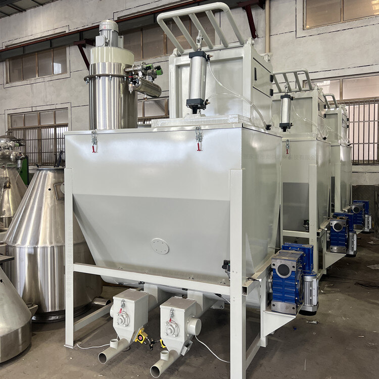
- The powder metering system tells you about the introduction of the mixing and drying machine
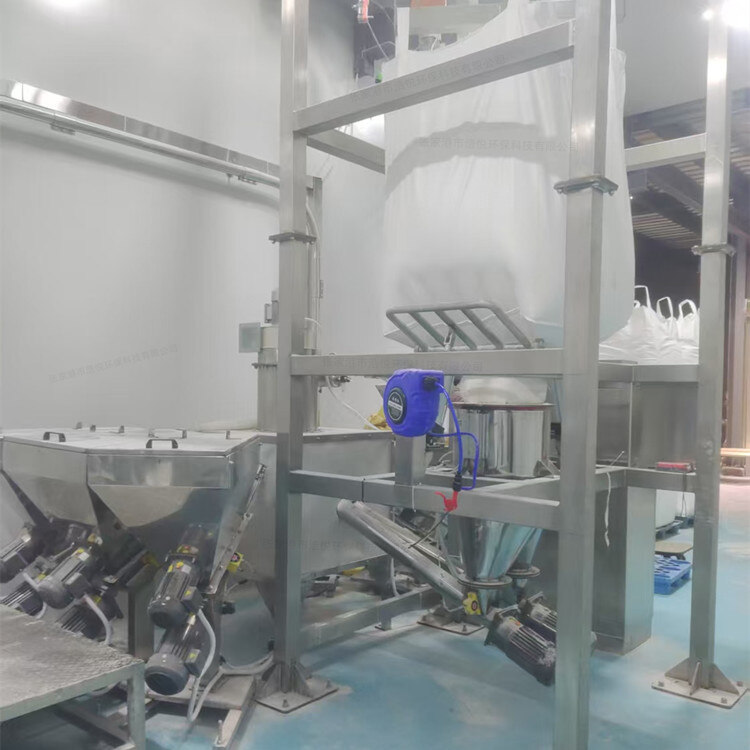
- 1000kg vacuum feeding machine
- Fully automatic small material batching system
- Research on Innovation of Automatic Weighing Machine Technology
- Design and operation of automatic batching system using PLC, industrial computer and frequency converter

Negative pressure conveying metering structure diagram
- Category:Automatic metering and conveying equipment
- Hits:285次
- Release Date:2025-06-30
- Share:
- Inquiry
- Details
In modern industrial production, there are extremely high requirements for precise conveying and measurement of materials. The negative pressure conveying and metering system, as an efficient, environmentally friendly, and precise material handling solution, has been widely used in many fields. The core negative pressure conveying metering structure diagram clearly shows the architecture and operational logic of the entire system, which plays a key role in understanding and optimizing the system.
1、 Basic architecture of negative pressure conveying metering system
The negative pressure conveying and metering system mainly consists of six core parts: gas source system, feeding system, conveying pipeline system, metering system, separation and dust removal system, and control system. Each part cooperates with each other to ensure stable conveying and accurate metering of materials. In the negative pressure conveying metering structure diagram, these systems are presented in a specific layout and connection method, intuitively showing the flow path of materials and the functional relationships of each part.
(1) Gas source system
The gas source system is usually located at the starting end in the negative pressure delivery metering structure diagram and is the power source of the entire system. It is mainly composed of a vacuum pump or a negative pressure fan, responsible for creating a negative pressure environment inside the conveying pipeline. The vacuum pump extracts air from the pipeline through mechanical operation, making the pressure inside the pipeline lower than the external atmospheric pressure, forming a pressure difference, and providing power for the transportation of materials. In the structural diagram, the gas source system is connected to the conveying pipeline through a well sealed connecting pipe, ensuring stable airflow into the pipeline and pushing the material forward. Different types of gas source equipment will have corresponding markings in the structural diagram, such as Roots vacuum pumps, water ring vacuum pumps, etc. The selection is determined based on factors such as conveying distance, material characteristics, and required negative pressure intensity.
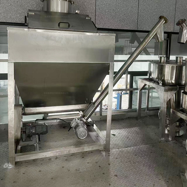
(2) Feeding system
The feeding system is responsible for introducing the materials to be conveyed into the conveying pipeline immediately after the gas source system. In the structural diagram, the feeding system includes components such as feeding hopper and feeding device. The feeding hopper is usually designed in a funnel shape, which facilitates the centralized storage of materials and smooth entry into the feeding device. There are various forms of feeding devices based on the shape of the material (powder, particle, block, etc.), such as spiral feeders, vibrating feeders, star shaped unloaders, etc. For powdered materials, the screw feeder can precisely control the supply of materials through the rotation of the screw; The vibrating feeder uses vibration to evenly drop the material into the conveying pipeline. In the negative pressure conveying metering structure diagram, the connection between the feeding system and the conveying pipeline is crucial, and it is necessary to ensure sealing performance to prevent external air from entering and affecting the negative pressure environment. At the same time, the connection part will be marked with relevant sealing technology and interface specifications to ensure the airtightness and stability of the system.
(3) Transportation pipeline system
The conveying pipeline system is the main part of the negative pressure conveying metering structure diagram, presenting a clear material conveying path. Pipelines are generally made of materials such as stainless steel, carbon steel, or engineering plastics, and are selected based on their corrosiveness, wear resistance, and other characteristics. In the structural diagram, pipelines are represented in the form of lines, and their diameter, length, and direction are clearly marked. The size of the pipe diameter is determined based on the flow rate and conveying speed of the material, usually between 50-300mm. The pipeline route should be kept as straight as possible, with fewer bends to reduce resistance during material transportation. If a bend must be set, a bend with a large curvature radius will be used, and the curvature radius and angle of the bend will be detailed in the structural diagram. Pipelines are connected through flanges, quick couplings, and other means, and these connection points are also marked in the diagram to emphasize the importance of sealing and connection strength.
(4) Measurement system
The metering system is one of the core components in the negative pressure conveying metering structure diagram, responsible for accurately measuring the material conveying volume. Common measurement methods include weighing and volumetric measurement. Weighing measurement is achieved by installing weighing sensors at specific locations in the conveying pipeline, such as weightlessness scales, belt scales, etc. In the structural diagram, the weight loss scale is usually represented as a structure with a silo and a weighing sensor. During the process of conveying materials from the silo to the conveying pipeline, the weight of the silo is monitored in real time by the weighing sensor, and the conveying amount of the materials is calculated. Volume measurement utilizes flow meters and other equipment to measure the flow velocity and cross-sectional area of liquid or flowable powder materials in pipelines, obtaining the volumetric flow rate of the material and converting it into mass flow rate. In the structural diagram, the measuring system is closely connected to the conveying pipeline, and its installation position has been carefully designed to ensure that the accuracy of measurement is not affected by the flow state of materials and changes in pipeline pressure. At the same time, the accuracy level and measurement range of the measuring equipment will be marked. For example, the accuracy of a certain weightlessness scale can reach ± 0.5%, and the measurement range is 0-1000kg/h.
(5) Separation and dust removal system
The separation and dust removal system is located at the end of the conveying pipeline and is in a critical position in the negative pressure conveying metering structure diagram. It mainly consists of equipment such as cyclone separator and bag filter, used to separate the conveyed materials from the air and purify the discharged air. The cyclone separator uses centrifugal force to separate materials from the airflow. Heavier material particles rotate and fall along the inner wall of the separator under the action of centrifugal force, and are collected in the bottom bin. In the structural diagram, the cyclone separator is presented as a cylindrical structure with specific shapes and sizes, marked with the positions and specifications of the inlet, outlet, and discharge ports. The bag filter purifies the dust containing gas that has been preliminarily separated by the cyclone separator through a filtering bag. Small dust particles are intercepted on the surface of the bag, and the purified air is discharged from the air outlet. In the figure, the bag filter will display in detail the quantity and material of the bags, as well as the structure of the dust cleaning device, such as the connection of the gas source and the arrangement of the blowing pipes for the pulse blowing dust cleaning system. The separated materials are transported to the next process through a discharge device, which is also marked and described in the structural diagram.
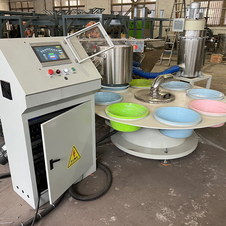
(6) Control system
The control system is like the "brain" of the negative pressure delivery metering system, connected to various systems through circuits in the structural diagram, to achieve automated control and monitoring of the entire system. It is centered around a programmable logic controller (PLC) or industrial computer, paired with a human-machine interface (HMI). The operator inputs parameters such as material conveying volume, conveying speed, and measurement accuracy through HMI, and the control system automatically adjusts the pressure of the gas source system, the feeding speed of the feeding system, and the working mode of the measuring system based on these set values. In the structural diagram, the signal transmission lines between the control system and other systems will be distinguished by different colors or line styles to clearly display the flow of data. At the same time, the connection relationship between each sensor and actuator and the control system will be marked, such as the pressure sensor feeding back the pressure signal in the conveying pipeline to the PLC, which controls the speed of the vacuum pump based on the signal; The weighing sensor of the measuring system transmits the weight data of the material to the control system, and the control system adjusts the operating status of the feeding device accordingly to ensure accurate conveying and measurement of the material.
2、 Interpretation of the workflow of negative pressure conveying metering system
Based on the structure diagram of negative pressure conveying measurement, the workflow can be clearly summarized as follows: the air source system is started, and the vacuum pump or negative pressure fan starts to extract air from the conveying pipeline, gradually reducing the pressure inside the pipeline and forming a negative pressure environment. When the set negative pressure value is reached, the feeding system starts working, and the material slowly enters the conveying pipeline from the feeding hopper through the feeding device. Under negative pressure, the material mixes with air and flows along the conveying pipeline towards the end.
During the material conveying process, the measuring system measures the material in real-time. If using weighing measurement, weight loss scales and other equipment to continuously calculate the material conveying volume based on changes in the weight of the silo, and feedback the data to the control system; If it is a volumetric measurement, the flow meter calculates the volumetric flow rate based on the flow rate of the material and pipeline parameters, and then converts it into mass flow rate and transmits it to the control system.
When the material reaches the end of the conveying pipeline, it enters the separation and dust removal system. Firstly, the cyclone separator utilizes centrifugal force to preliminarily separate materials and air, with heavier material particles falling into the bottom bin. Next, the gas containing tiny dust enters the bag filter, where the dust is intercepted and purified before being discharged from the system. The separated material is transported to the subsequent production process through the discharge device.
Throughout the process, the control system continuously collects operational data from various systems, such as pipeline pressure, material flow rate, equipment operating status, etc., and compares it with preset parameters. Once a deviation occurs, the control system immediately issues instructions to adjust the operating parameters of the corresponding equipment, ensuring stable and efficient operation of the system, and achieving precise negative pressure conveying and metering of materials.
3、 Application examples of negative pressure conveying metering structure diagram in different industries
(1) Chemical industry
In the production of chemical raw materials, it is often necessary to transport various powdered or granular raw materials, such as plastic particles, chemical powders, etc. Taking a plastic pellet production plant as an example, its negative pressure conveying and metering structure diagram shows the complete conveying and metering path from the raw material storage warehouse to the injection molding machine. By using a precise measuring system, we ensure that the amount of plastic particles delivered to the injection molding machine each time meets the production process requirements, ensuring the quality stability of plastic products. At the same time, a good separation and dust removal system effectively avoids the pollution of plastic dust to the environment, ensuring a clean production environment in the workshop.
(2) Food industry
In the field of food processing, negative pressure conveying and measuring systems are commonly used to transport raw materials such as flour, sugar, salt, etc. Taking a large bread production enterprise as an example, in its negative pressure conveying and metering structure diagram, the feeding system adopts specially designed feeding hoppers and feeding devices to prevent materials from getting damp and contaminated. The high precision of the measuring system ensures the accurate ratio of various ingredients in the bread recipe, thereby ensuring the consistency of bread taste and quality. The separation and dust removal system uses food grade filter materials to meet food hygiene and safety standards, preventing dust from contaminating food.
(3) Pharmaceutical industry
The pharmaceutical process requires extremely high precision in material transportation and measurement, as well as strict standards for hygiene environment. In the negative pressure conveying and metering structure diagram of a pharmaceutical factory, the conveying pipeline is made of 316L stainless steel material, and the inner wall is polished to prevent material residue and microbial growth. The accuracy of the measuring system can reach ± 0.1%, ensuring the precise proportioning of drug raw materials and guaranteeing drug quality. The separation and dust removal system is equipped with efficient sterilization filters, and the discharged air meets the requirements of GMP (Good Manufacturing Practice) to prevent cross contamination during the drug production process.
The negative pressure conveying metering structure diagram, as a key tool for understanding and applying the negative pressure conveying metering system, clearly demonstrates the system architecture, workflow, and collaborative relationships among various parts. In a wide range of applications across different industries, it plays an indispensable role in achieving precise material transportation and measurement, ensuring efficient and environmentally friendly production processes. Through in-depth research and optimization of the structural diagram, the performance of the negative pressure conveying and metering system can be further improved to meet the constantly developing industrial production needs.